Gimbal project
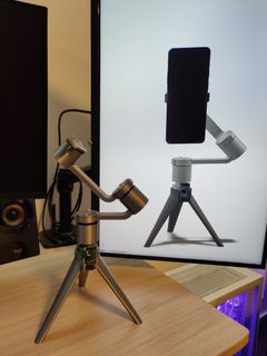
This project has started - like many others - with me wishing to have a gimbal to shoot smooth video on my phone. But, as it often happens, just going out to the store to buy one sounded too easy, so I decided to make my own. And I am glad I did, this project has been one of the most interesting to work on so far and a great opportunity to do some "real" mechanical engineering for the first time.
Hardware setup
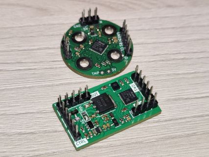
First, let's cover the electronics setup for the project. I had an option to either combine everything on a single PCB or have them separate. I decided to go with the second option because my goal here was to build a modular solution. I split the electronics as follows: motor assembly would be a separate part, controlled via UART or PWM. This would later allow me to reuse the whole motor assemblies to act as servos for other projects if I ever need them. The main board contains the main power supply together with an IMU for determining orientation as well as the microcontroller to connect to everything else in the system. And finally, the control board is its own separate part, communicating with the main board over UART to send user inputs - such as joystick movements and button presses - to then be processed by the main board and turned into motor angles for the motor drivers. The idea behind a separate control board was to have different interchangeable boards - for example, a simple one with just a joystick for orienting the camera and a couple buttons to control everything else and a more sophisticated one with a small OLED screen for better user experience.
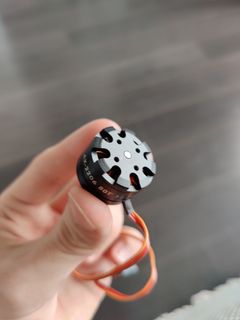
For this project I was going to need some motors and something to drive them. I picked a couple cheap brushless motors online (which later turned out to be a mistake) and proceeded on designing some electronics.
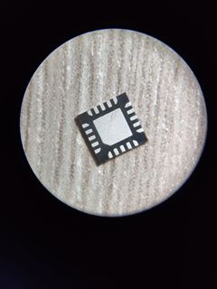
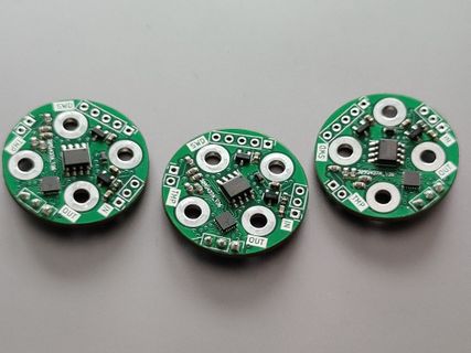
On the right is TMC6320 - an awesome and tiny (just 3x3mm!) brushless motor driver. It can work at voltages up to 11 volts and currents up to 2 amps. At its core, it's actually not a very complicated device - six transistors to control the motor together with some protection circuitry, so the inputs are quite simple as well. Six input pins are used to open six corresponding transistors. Three of them connect the motor coil to ground and the other three to bus voltage. By modulating the time each of the transistors is open we can precisely control the position of the motor.
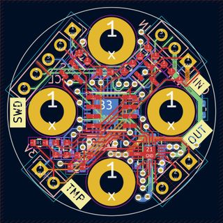
Next was PCB design. The motors I picked were only 28mm in diameter and has four mounting holes but I managed to fit all the components on a PCB quite easily since all of them were pretty small. Aside from the drivers I added a magnetic encoder to keep track of the motor's orientation and, of course, a microcontroller to process everything and control the drivers. The board also includes some power regulation, level shifting and a place to solder a thermistor to keep motor temperature under control. Special attention was paid to laying out power traces as they would see some current going through them.
Communication
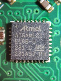
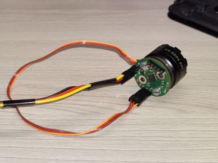
Space is at a premium inside a device like this. This means you have to be very conscious about the free space you leave within your device when designing its outer case and also the dimensions of everything that goes inside the device. A painful discovery was that regular pin headers are pretty bulky and don't easily fit in tight spaces but I decided to go with them anyway since they're easily available and you can make your own cables in any length and pin count. That meant, however, that I needed to keep the number of cables to a minimum and I found an interesting solution for UART. The microcontrollers I've chosen, Microchip SAM L21 have universal serial communication modules that can act as USART (Universal Synchronous/Asynchronous Receiver and Transmitter), I2C and SPI. One of the features of USART modules is collision detection for UART similar to I2C multi-master configurations which allowed me to use only 3 wires to connect all three motors to the main board: ground and voltage to carry power and a single bidirectional data wire for communication.
Software
Software is what makes everything work in this device. From taking user inputs, measuring and estimating handle orientation to calculating inverse kinematics and keeping the motors in the set position, all that is handled in software. Each component runs its own custom-made firmware and uses UART to communicate with other boards in the gimbal. An unexpected but interesting challenge was optimizing motor firmware for latency. AS5600, the magnetic encoder has a sampling time of 150µs. This means the sensor can produce a new measurement 6666 times per second. Even though operating at such frequencies brings little to no benefit for responsiveness, it felt like a good idea to try to exceed that. This gives us 150µs or less to read the data from the sensor and do all the processing required. Even at the highest I2C clock frequency supported by the sensor at 1MHz reading the data takes about 100µs, leaving 50µs for processing. In those 50 microseconds a lot needs to happen but I actually managed to do all the calculations in under half the time by optimizing the code and moving the heavy computations away from the microcontroller by precomputing the sine table during compile time.
Mechanics and hardware
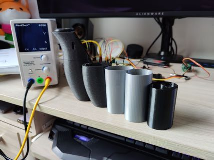
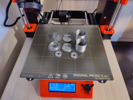
This was the first time I did something even remotely related to mechanical engineering. Mistakes were made - sometimes quite obvious - but this was a great opportunity to learn how things are done and make something cool in the process. I got a chance to experiment a bit with ergonomics (left), do quite a bit of 3D printing and optimize the design - a lot. The most challenging part by far, however, was to shrink the outer dimensions of the device as much as possible while maximizing internal space that can be occupied by batteries, electronics and other components.
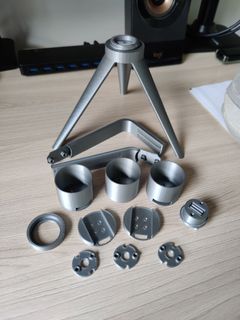
Gimbal was designed to be modular. The whole top part with the motors is hot-swappable and is held down by a single large 3D-printed nut. Two variants are in development - one with brushless motors and other is using servos for applications where having low weight is important. The firmware detects which one of the two is connected and uses the appropriate protocol for it - UART for motors and PWM for servos. Same story repeats with the control board, although swapping the modules requires disassembling the handle.
Mechanically the gimbal is designed to be as simple as possible and assembled of as few parts as possible. Getting the required strength from plastic parts was also a challenge, requiring many iterations and prototypes to land on the design that's simple, functional and sturdy enough to support a smartphone. The motors I picked initially turned out to be not only underpowered but also quite difficult to use so the gimbal had to be redesigned for motors with a hollow shaft.
Kinematics
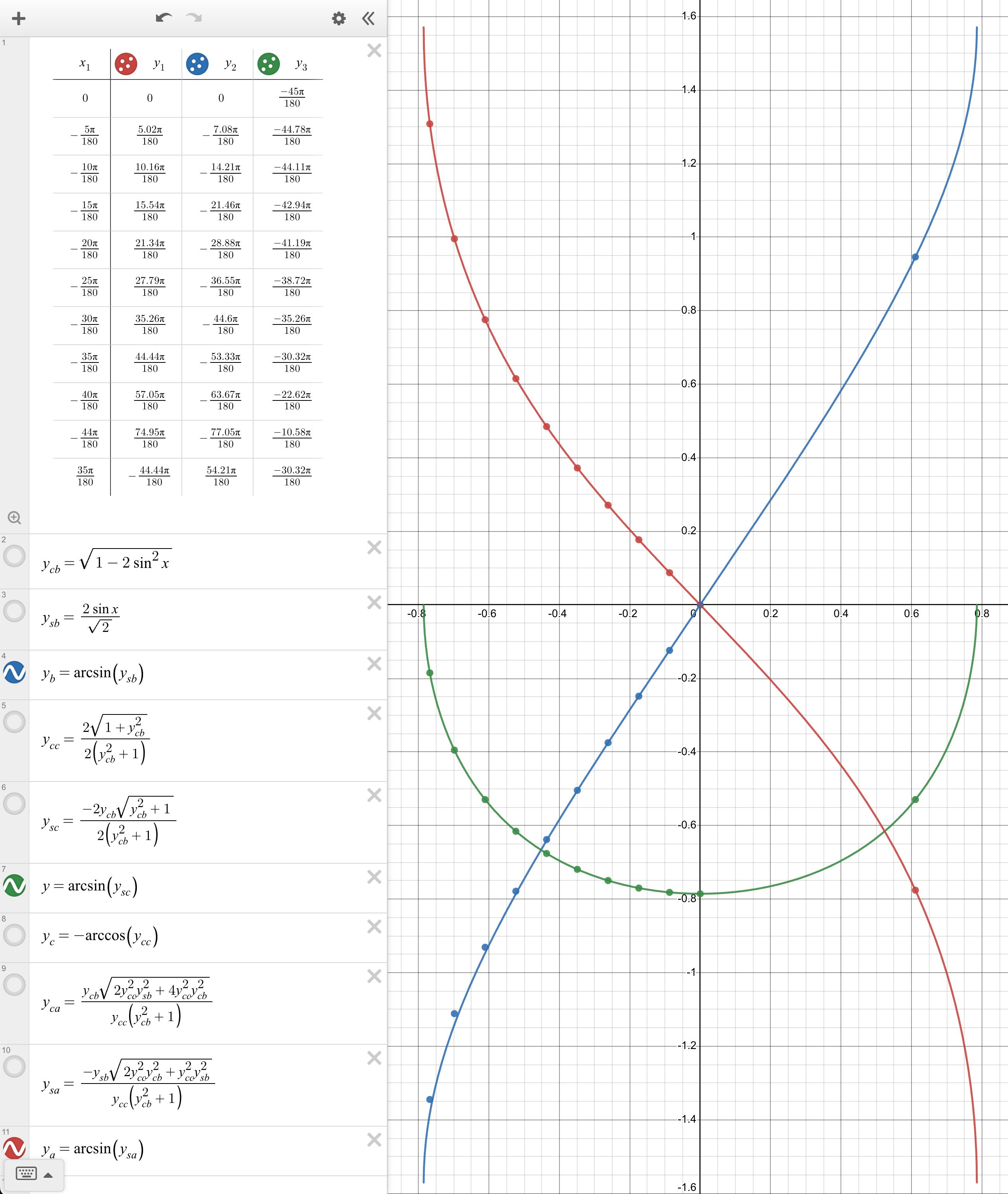
A decision I made on this project was not to have all motors' rotational axes orthogonal to each other. The reason was simple - the gimbal can be made dramatically smaller using this configuration. However, this raises an issue of controlling the motors as one motor's rotation starts affecting others so they need to correct. This is a problem of inverse kinematics - we need to calculate the angles of all the joints knowing the start and end orientation. Thankfully, this particular situation is quite easy to solve for as it only has three degrees of freedom and three joints. This configuration has an analytical solution and by calculating the rotation matrices and setting them equal we can get the movement equations. By solving for angles, we can get the formulas for calculating each of the motors' angles for any given orientation. Those equations were then checked against a CAD model to verify the calculations were correct (left).
Conclusion
This project has been a great way to learn many things from firmware optimization and basics of mechanical engineering to inverse kinematics and sensor fusion to estimate the orientation of the device given the readings from accelerometers and gyroscopes. This project is still in development and things are likely to change. The goal is to have the project completely open source, including source code together with 3D models and PCB designs to serve as a learning opportunity and inspiration for anyone who's interested in contributing or simply building a device of their own.